Controlling 5V relay with Raspberry
Relay
In todays article, we are going to have a look at an electronic component called relay. In case that you have never heard of it, it is simply a mechanical switch, that can be controlled by low level voltage (starting from usually 5V) and that can switch much higher voltages, for example the one you have at a plug at your home (110/120/220/230V depending on where you live). Inside of a relay, there is a mechanism made of a coil and a piece of metal, that can move from one side to the other. See the picture below to better imagine the inside of a relay.
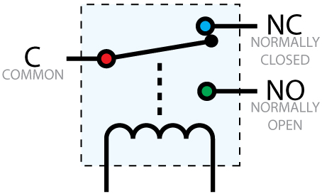
C input is for high voltage current, so lets say for 230V. This input is normally connected by the mentioned piece of metal with NC output, which stands for Normally closed. In case you want to use a relay as a switch, which is by default in OFF mode, you will leave NC as it is, so the voltage from C is not going anywhere. NO output, that stands for Normally opened, is the place where you connect some electronic appliance, such as a light bulb, heating or whatever you wish to be in control of. But as we said, C is by default connected no NC so whatever is connected to NO will be OFF by default. C, NC
These three pins are those with screws on top of them, which will help you to attach the wires of an electric appliance, you will be controlling.
Now comes the interesting part of controlling the relay. There is another circuit in relay, this time low level voltage, which controls if a current will flow through the coil or not. If there is a current flowing through the coil, it creates an electromagnetic(EM) field, which as we know attracts metal. As I mentioned at the beginning, there is a piece of metal inside the relay, which attracted to the coil, when the EM field is present and causes it to move from NC position to NO position.
This circuit is controlled also by three pins. They are those traditional small pins coming out of the relay board. Those three pins are marked as VCC - which will be connected to 5V source, GND - which will be connected to the ground and IN which will control if the coil should produce EM field or not.
Which relay to buy
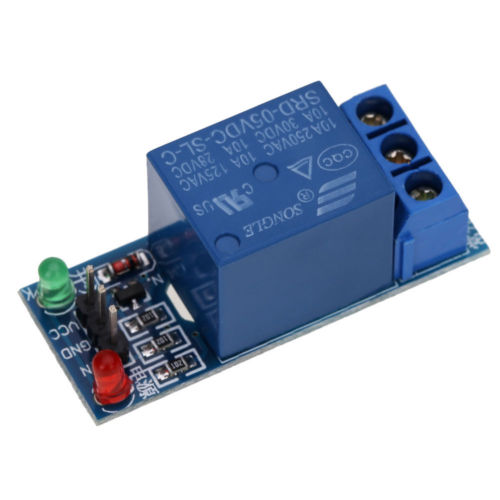
Now when searching for a relay on the internet, you will find thousands of different types. Search for an Arduino/Raspberry 5V relay. Those 5V are important as one of the characteristics of a relay is its working voltage. RaspberryPi can give you 3.3V or 5V. Most of the relays you will find need at least 5V, but some of them can work even with 3.3V so don’t forget to check this when buying one. They come as a single relays or on a board where you have 2/4/8… of them. Their price starts at around 1$ on Ebay, so you can definitely buy at least two of them to experiment with.
I have bought 1 channel 5V relay 1280 2560 ARM PIC AVR DSP
Connecting it to Raspberry
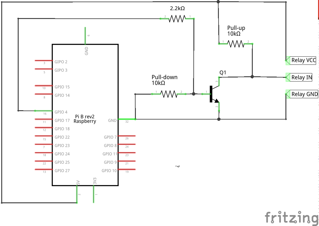
As I already said, Raspberry will control the relay, so we will connect it to control part of the relay - VCC to Raspberry’s 5V output, GND to ground and IN will serve to control it. You might be tempted to just connect the IN to GPIO in OUTPUT mode and switch it from high to low, but this will unfortunately not work. Relays are usually so called GROUND/ZERO/LOW LEVEL ACTIVATED which means, that the IN pin must be connected to ground to turn the relay ON and connected to 5V (or disconnected/floating) to be OFF. Therefore we will need to create a small helper circuit to be able to connect the IN pin with ground or 5V using our Raspberry. We will need a NPN transistor, that will serve as a switch, two 10KΩ resistors, that will serve as pull-up and pull-down resistors and one 2.2KΩ resistor.
Pull-up & Pull-down resistors
You might be asking what is that pull-up/down resistor I just mentioned. When dealing with with sensors, relays and any other electronic components, that can be controlled, we always want to be sure that we know in which state they are (ON/OFF). This is almost always done by switching the voltage between the 5V and GROUND on some kind of IN/CONTROL pin. However, there are situations, when you can not be sure, what voltage is on the pin, that could lead to unexpected behavior, for example if you leave the control pin just as it is, not connected to anything. It might seem like if some pin is not connected, there would be no voltage on it, so it would be the same as connecting it to ground, but no! There can be some electric charge “flying” it the air, that will “sit” on the pin and suddenly turn your circuit ON and then it can again “fly away” so your circuit can go mad switching between ON and OFF multiple times. Such a state when the pin is not connected is called FLOATING state and we need to make sure that or control pins will never happen to be in such a state.
Here comes the pull-up/down resistor. It is used to make sure, that in default state, there is always high voltage on the pin, e.g. 5V on the input pin (in case of pull-up) or that the pin is grounded (in case of pull-down). These resistors have high resistance, usually 10KΩ, cause we do not want to have a high current floating through them, which would be plain wasting of energy and also, we want to be able to “override” the default settings, by having an optional circuit branch, with lower resistance. Circuit always go by the way of lowest resistance, so if we let it go through such a lower resistance branch, the pull-up/down branch will be kind of ignored.
Control circuit
In our case, we want the relay to be in OFF mode by default. Therefore we will use a pull-up resistor for the IN pin. Then we will have a transistor, serving as a switch, that will connect the IN pin to GROUND on our demand. We want this transistor to be CLOSED by default, so we will connect a pull-down resistor to it.
The transistor itself will be controlled by a GPIO in OUTPUT mode. Since a big current could potentially destroy our transistor and only low current is needed to open it, we put a 2.2KΩ resistor between the GPIO and transistor’s base. Transistors collector is connected to IN pin and emitter to GROUND. So when the transistor is opened (GPIO will be set to HIGH) the relay will turn ON, when the transistor will be closed (GPIO set to LOW), relay will be OFF.
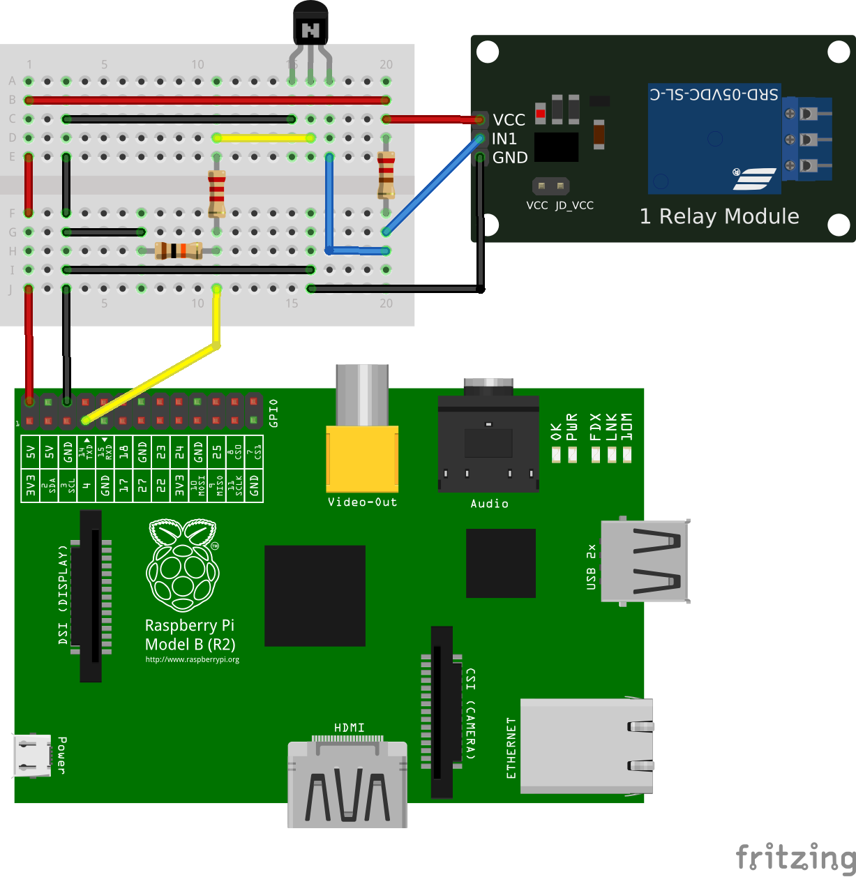
See the image below for details on how to connect the relay to Raspberry.
Controlling the relay
Now we have the circuit ready, so lets test it. First lets just simply use a gpio command line program to turn the relay on and off.
First lets set the GPIO to OUTPUT mode - turn on the command line and write:
gpio mode 7 OUT
Let’s check if it is really in OUTPUT mode by writing:
gpio readall
Which will show a schematics of your Raspberry with all pinouts, their number, mode and current value. Now turn the relay ON by setting the GPIO to HIGH:
gpio write 7 1
The relay should turn ON. Horay! Now turn it back OFF by setting the GPIO to LOW:
gpio write 7 0
Voila! You are now in control of the relay. But how about writing a simple python program, that would switch the relay on and off by pressing an ENTER key.
#!/usr/bin/python

# Import required Python libraries
import RPi.GPIO as GPIO

# We will be using the BCM GPIO numbering
GPIO.setmode(GPIO.BCM)

# Select a control GPIO
GPIO_CONTROL = 17

# Set CONTROL to OUTPUT mode
GPIO.setup(GPIO_CONTROL, GPIO.OUT)

# Main function
def main():
  # Start by setting the relay to OFF
  relayState = False
  GPIO.output(GPIO_CONTROL, relayState)
  print('Relay is OFF')
  try:
    # Repeat till the program is ended by the user
    while True:
      # Wait while ENTER is pressed
      # This is a small hack, raw_input() can read keyboard input until you press ENTER and save it to a variable, but we dont care about other keys to be pressed, so we don't
      raw_input()
      # Toggle the relayState value
      relayState = not(relayState )
      # Change the CONTROL output value
      GPIO.output(GPIO_CONTROL, relayState)
      # Print state to console
      if relayState:
        print('Relay is ON')
      else:
        print('Relay is OFF')
  # If the program is ended cleanup GPIOs
  except KeyboardInterrupt:
    GPIO.cleanup()

# Run the main function when the script is executed
if __name__ == "__main__":
    main()
Call this file relay_control.py and run it
python relay_control.py
Every time you press ENTER, relay will switch from OFF to ON and the other way round. Also, on every switch, there will be a message printed into the console reading Relay is ON/OFF. Give it a try and enjoy creating cool projects with relays and Raspberry!
The code, schema and breadboard wiring is also available on my GitLab